soviet PPSh-41
FEBRUARY 2010
The PPSh-41 is a Soviet submachine gun from WWII designed by Georgy Shpagin. It is a cheap, reliable, and simplified alternative to the PPD-40. Commonly known as "papasha" (Russian: папаша), meaning "daddy".
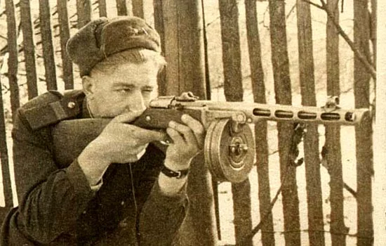
I’ve always loved the look of this gun so I have decided to try something ambitious by re-creating this one as accurately as possible. I plan to make it as functional as styrene plastic will allow. My web research has produced actual machinists diagrams of most of the parts of the gun. Others I will have to reverse-engineer from photos.
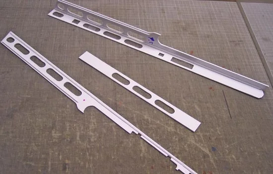
I cut out the sides of the barrel shroud as individual panels and join them together like a box. I glued in a thin strip on the inside joints for support.

I glued the sides on to the top piece (a “u” shape) and then glued in a barrel support and the muzzle end. Before I glued the bottom, I painted the inside as it would be next to impossible to paint it when completed.
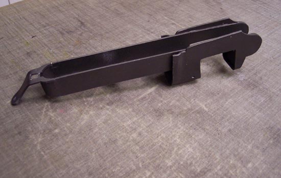
The lower receiver came together pretty fast so I don’t have any progress photos. It’s built like a box, the hardest part was the curved section at the back. I bent some heated plastic around a bottle with the right diameter and then glued it to the rest of the box. The big notch is where the drum magazine fits. Most of the rest of it will be inside the wooden stock.

The breach block was formed by sandwiching a bunch of 3mm styrene sheets together. The other piece is the latch that locks the upper receiver down to the lower receiver. I heated a sheet of plastic with the heat gun, stretched it over the wooden form. I then cut a long rectangular slot out of the top and attached a small piece of plastic that I heat bent around a pencil. This area will house a compression spring that keeps the latch closed.
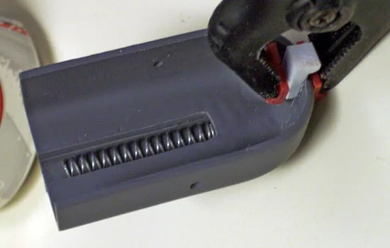
A “L” shaped piece was glued on to the end that will fit into a slot on the lower receiver. Note the spring in place.

On the REAL receiver, a small “U” shape is cut into the top and the metal is bent up to form a catch for the spring. Since it would be extremely difficult to replicate this with the plastic, I just cut a piece and glued it on.
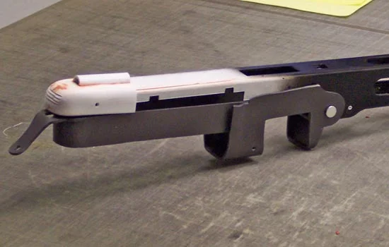
The completed latch! You can see the slot where the tab is inserted on the lower receiver. The white dot on the side of the latch is a pin that goes all the way through both the latch and Upper receiver. The pin actually runs in a small slot on the receiver that allows it to move back and forth about 1/4″…enough for the latch to disengage. The upper receiver swings freely to access the internal mechanisms to come.
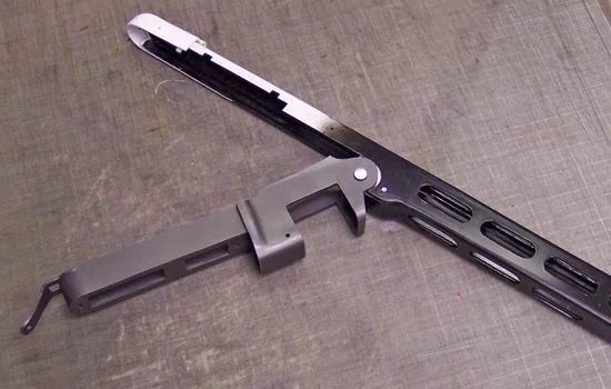
You can see how the upper receiver latch locks into a notch on the lower receiver.
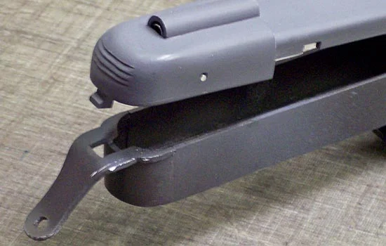
Using a cutaway poster as a guide, I built the trigger assembly internal parts and the rear sight. The rear sight is pretty clever as it uses an inverted “v”-shaped piece of metal as a rocker spring to toggle two different sight apertures. At this point, I wasn’t completely sure what these parts did or fit together.

The spring guide is a rod that acts as a guide for the bolt as it moves in the receiver. I used a long bolt, trimmed down the head with a grinder, and sheathed it with an aluminum tube. The bolt is pushed backward by recoil and hits a plastic stopper. For this I used laminated plastic.

The bolt pulls rounds out of the magazine, pushes them in the breach and fires them. The metal strip on top is the extractor spring which I made out of metal from a picture frame.

This was made by laminating some 20-odd sheets of plastic together. Now it is a SOLID hunk of plastic!
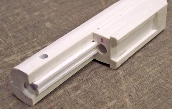
Another view of the bolt.
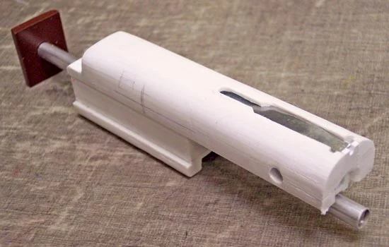
The bolt slides on the spring guide as shown. A spring will fit between the bolt and the brown piece to move the bolt forward.
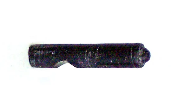
The firing pin fits in the bolt face. For this I cut off a piece from a toy, put it in my hand drill and used a blade to lathe the tip. This piece is only 1/2″ long.
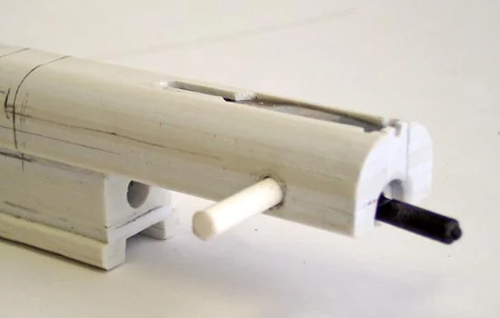
When it’s inserted, another pin locks it in place.

The safety on the PPSh-41 is a small sliding latch that locks the bolt in an open or closed position.

It utilizes a small spring powered plunger to lock it in place. I had trouble finding a spring that small so I cut off a small piece of a rubber octopus’s tentacle to push the plunger.
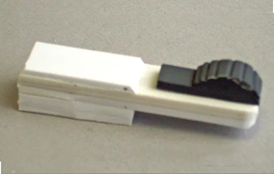
The switch slides into a slot on the bolt arm and locks into two positions.

After I marked the positions of the bolt in the receiver, I drilled, filed and cut the hole for the handle.

Once I glued it in place, a little sanding made it appear to be one piece. The handle is surprisingly solid although the spring I’m trying to find shouldn’t cause that much torque.

The selector switch (allowing either semi or full-auto fire) was a bit of a mystery for me. All I had to go by were some long shots and a cutaway drawing.

Assembled I think it’s close…the actual construction is my best guess.

The trigger assembly involved much trial and error. I barely understand the mechanisms but everything seems to work!

There isn’t any extra space in the trigger box so everything had to fit just right.
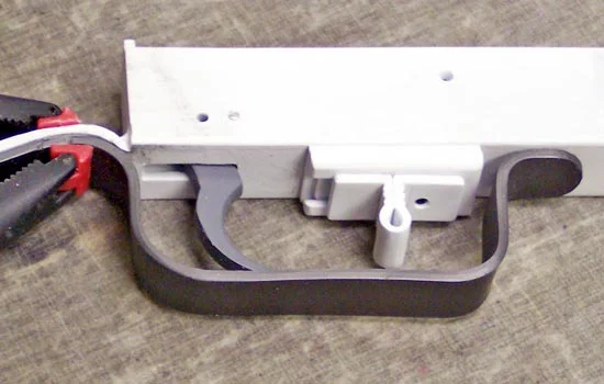
Even though it’s only plastic, everything seems to function.
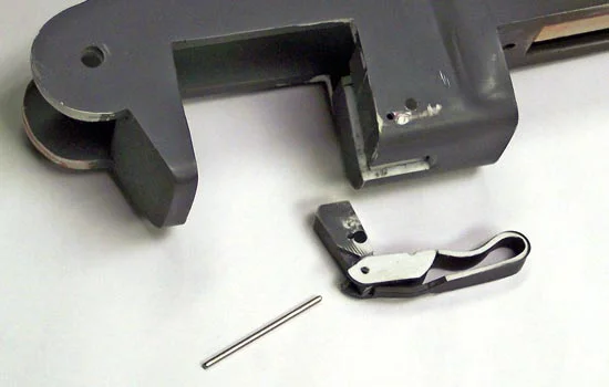
The magazine latch was tricky to figure out but was in fact brilliantly simple in design. You can see a mis-drilled hole when I was trying to figure out the correct position.

The latch in position shows how the latch rotates and, with pressure from a hidden spring, locks the magazine in place. The folding handle flips down and then moves the latch away from the magazine, allowing it to be removed.
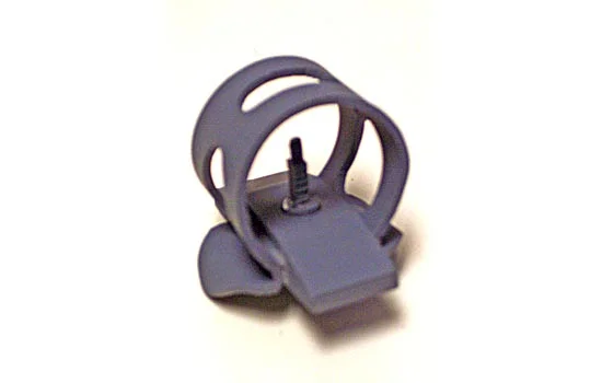
The front sight came together very fast (about 1 hour) so I forgot to take pictures along the way. I didn’t have any good reference for the sight post so I modeled it after the front sight off the AK-47. The flat part is laminated styrene with a hole drilled for the post. The ring was heated plastic stretched around a bottle.
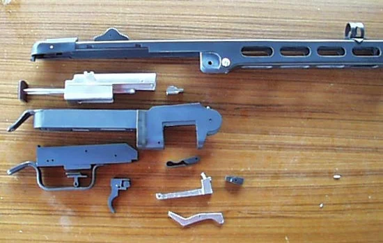
Here are all the parts I have completed in relative position to each other.

I found a plastic tube with the right outer dimension for the barrel.
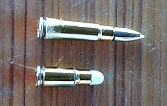
I dummied up a bullet from another kit with the same caliber. I cut down the AK 7.62 x 39 to become the 7.62 x 25.

The dummy bullet that I made fits snugly in the breach.

All the parts for the barrel assembly.

After making a magazine that was too large for the opening, I was able to use it as a form for the new one. Using a heat gun I was able to press the grooves directly into the surface of the top and bottom of the new magazine.

For the side of the drum, I used a plastic jug as the form and pressed the groove directly into that.

More putty to hide the seams on the assembled magazine. It didn’t turn out as crisp and machined as I would’ve liked but I figure once painted and weathered it will look like it’s been in a few battles!

The bracket will mount over the drum opening and allow the bullets to feed into the gun.
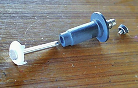
The center pin has a ratchet cap that holds the lid in place as well as allows the center spring to be wound. This was drill-lathed out of laminated plastic.

Inside the magazine is a track that feed the rounds into the gun. I was even able to heat form a groove in the track itself…just like the real one!

This scoop is inside the opening of the magazine and guides the bullets out of the track. It was also (carefully) heat-formed.

This swiveling roller arm attaches to the spring case to push the bullets out of the drum.

The roller arm attaches the spring case that sits in the middle of the track.

You can see how the clockwise rotating pusher arm runs through the tracks to feed ammo. Remember, I had no plans for the interior and it all had to be reverse engineered using cutaway drawings and photos.

I originally intended to make the stock out of birch like the real gun, but pine proved to be more economical.

Since I intended to router out the butt compartment and the slot for the receiver in front, I made the stock from two pieces of 3/4″ pine, later to be glued together.
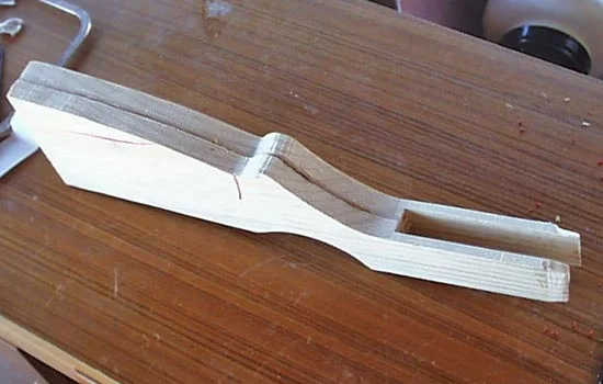
Even though I built everything to spec, because of my materials the receiver had to be thicker walled. In other words, the receiver wouldn’t fit! I used some 1/8″ basswood to widen the receiver opening and then laminated all the parts together.

Then, with the assistance of my trusty wood plane, I carved the rough shape of the stock’s contours.

I had to dremel out a notch above and below the grip to mount the trigger assembly.

The lower receiver in place. A bolt passes through the tongue on both receiver and trigger assembly, locking them into the stock.

The left side of the stock houses the rear sling bracket. I dremeled out this area to match a styrene bracket I had cut.

I inset the butt of the stock to accept the butt plate. I used the stock to heat form the sides of the butt plate out of styrene.

I used a loop of wire to join the ends of the styrene in place while the glue dried and glued the end of the butt plate to the sides.

The edges were sanded off and smoothed and the screw holes were beveled.

I glued in a small lip on the inside of the hatch and used a nail as a pin for the hinge.
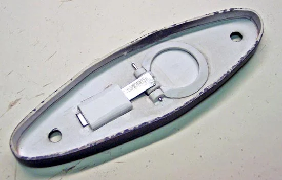
With no reference for the inside of the butt plate, I used a piece of steel as a spring to keep the door under tension.

The last thing to do was to stain and shellac the stock. Here are the final photos of this exhausting project!

This gun can be disassembled just like the real one…nothing is glued that shouldn’t be.

Eventually I will buy brass for the magazine and cast plastic bullets to fill the magazine.
